

Mustang Maniac has NOTHING to do with DeAgostini. We can NOT help you obtain parts or grievances. We bought the kit just like you. When we had issues we had to sort it out ourselves too.
Please contact them on the following:
https://www.deagostini.com/uk/myarea/p/contact-us
customer.service@deagostini.co.uk
020 3868 7521
Total number of Issue to complete the build = 100.
Started 24/1/2016 – Completed 20/11/2017
Cost Per Issue / Per Week = £8.99 That’s the best part of £900 total
This is a guide to how we are getting along with the DeAgostini die-cast model. This will be available on a weekly basis or via a monthly shipment of four issues each month. The issues will contain step by step build guides, articles on Shelby, Mustang Other muscle cars as well, so it should be an interesting read too. We will be adding to the page on a descending order, but we won’t be showing every single screw or part fitting as that could be a blog on its own. But we will show the good and exciting bits we hope.
There is a couple of links we will share with you the first is the actual website for the model or click here:
https://www.deagostini.com/uk/collections/buildshelbymustang/
The second is the company forum of what it’s all about to build one maybe help if you have any issues or click here:
http://forum.model-space.co.uk/default.aspx?g=topics&f=386
Shelby Model Build Pros & Cons
Pros
We enjoyed building it.
Paint and metal parts finished to a high quality. All painted parts colours match.
Some exceptional detail work for the interior and hood pins.
Extra screws supplied with each pack sometimes used and a nice touch.
Big and very heavy model.
Magazine articles are good, but not always related to Mustangs.
Cons
Expensive. Almost £900 total build cost.
Supplied screwdriver is rubbish.
Under hood detail poor – such as the incorrect firing order of the distributor cap, no starter solenoid.
Could of done with better colouring under the hood for engine parts instead of all silver.
Poor fitting of door hinges.
Distribution order of parts means having to store some parts for months at a time, from early issues, such grill from issue 1, the hood from issue 4, and doors from issue 10 etc.
No Batteries supplied.
Takes nearly TWO YEARS to complete.
Update 26/11/2017 – Completed
The final delivery of parts. Issues 97 – 100.

Issue 97
This issue there is roof liner supplied that you can do nothing with just yet so put it to one side. The task for this issue is to fit the doors which are held in place by a single screw! The hinge is located on the A pillar via two stubs and a hole for the screw. Unfortunately the holes on the A pillar are larger than the stubs by a little margin. The end result is a play in the door and can be moved up and down by a number of millimeters. This is pretty rubbish for a model that costs as much as this does.


We show here that the door when closing has to be pushed shut to fit under the gutter chrome trim to make it shut correctly. The door gaps are not brilliant as a result until you manoeuvre it about a bit. We would have thought that two screws to hold the door securely would be the way to go.


On the plus side how often are you really going to open the doors? not very often we suspect so once shut they are fine.
Issue 98
This issue we put the sun visors to the roof lining and the rear view mirror. Pretty simple snap into place with a screw for the rear view itself.


The headliner is just pressed into place on the roof. A note of warning here; when you turn the car over watch the aerial as it will be higher than the roof of the shell and will get bent if you are not careful.


This issue also sees a huge step – fitting the chassis and the shell together.
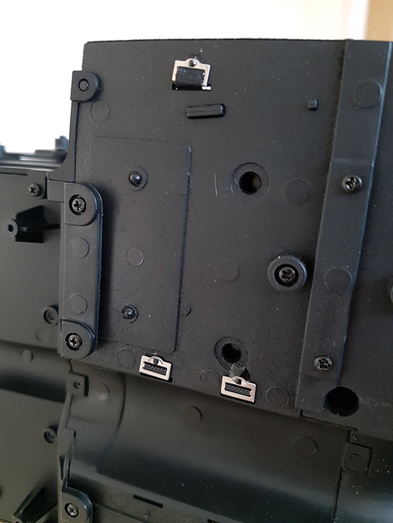
The chassis will need to be connected to shell via the remaining four wires.


We are also told at this point you will need to buy batteries! The batteries are LR44 or AG13 and you will need three of them. Again a model of this cost should supply the batteries with the issue, luckily we had a strip of these batteries laying around and cause us no hold up. The fitting of the batteries will not stop the issue being completed, but it can save you a whole heap of hurt if you have them now before you assemble the two main parts.


WHY?
We say this because we don’t rust anything until it’s tested. We fitted the batteries into the battery compartment and turned the circuit on via the tiny switch. On inspection we had a the left hand side set of rear lights not working. That’s the driving lights and also the stop lights. Fault finding process was to swap the wires over on the connections for the other side. Now the right hand side was not working and the left was; this means the light set and cable itself was fine. We swapped the wires back and traced the wire to the circuit board. It was here confirmed that the plug to the circuit board was fitted correctly, but one of the cables into the plug was not seated as low as the other side. We had to unscrew the circuit board from the chassis to get to the plug. A pair of tweezers were used to press the cable back into the plug. Tested the circuit again and all was working now we screwed the circuit board back to the chassis. We tested a final time the horn, working, the front/rear/stop lights were working, the gas pedal gave us a start-up and a revving engine which wasn’t exactly realistic, but about as good as you are going to get from that type of speaker fitted to the model. Now we can put the two parts together. We recommend that you remove the spare wheel from the truck at this point as it will move around in the trunk when you turn the model over.
The shell is fitted to the rear of the chassis making sure the filler pipe fits into the shell correctly. No pictures of this point as the model is heavy and needed both hands for this bit. With the shell and chassis parts clipped together at the back we could lower the rest of the body down towards the front.


Make sure all the wires are in place and hidden out-of-the-way behind the dash area where there is plenty of space before you press the two parts together properly. We managed this by using a screw driver to push them out-of-the-way.

To make the shell fit we had to slightly bend the radiator support section to allow the shell to drop down completely. Turning the car over to screw the bottom together need some more pressing into shape and holding while the screws located and screwed in tight.

Now we have a car together, another re-test of the electrics showed all was well.
Issue 99
This is a simple little section where we make the back up lamps by pressing the lenses into the housing and pressing into place and holding it in place via a simple screw behind the rear valance.


Issue 100 – The Final Issue
The rear number plate is screwed to the plastic rear valance. Take both the completed rear panel with the back up lamps (not the “Fog Lights” as they refer to them) and the valance to the back of the car and screw them both into place with four screws.


The last and final part is to press the rear bumper into place.


MODEL COMPLETED.
Lights:


Interior, Hood & Trunk:


Open Body:


Profiles:


Update 15/10/2017
Back to being on time now the latest batch of parts have arrived issues 93 – 96

Issue 93
This is the cowl section and again made of nice metal and is the last part of the metal body shell. The wipers from the previous issue will now be added to the cowl. the wiper will fit in only one way due to a key-way locating lug. A single screw holds the wipers in place.


The cowl is slotted into the top of the shell and attached via a couple of screws on the underside.


Issue 94
On this issue there is nothing to do except read the articles and store the rear glass (plastic actually) panel carefully.


Issue 95
This issue gives us the chrome surround to hold the rear glass in place as well as the aerial. The same principles are used for the trim as the front glass. start at the bottom and clip in working to the top.


The aerial has a key-way lug and single screw underside will hold it in place.


Issue 96
More chrome trim on this issue. There are no screws for this just simple press in fits. Start at the back bottom of the window rail and work up and around.


The last part is the sill kick panels which again only for one way round and just press into place.


Note:
In this issue 96-A and 96-B parts are mentioned which are the hinges for the doors. These were NOT in the issue. We can only assume that the hinges were correct when those particular issues were produced. Let us know if you have any issues with the hinges.
Update 8/10/2017
Back to being on time now the latest batch of parts have arrived issues 89 – 92

Part 89
It looks like we are now going to be working on the body shell again so there was no need for the chassis part. We needed the trunk section from the previous issue though. The first part was to apply the rear quarter extensions, this can only go on 1 way and is held in place by three screws from the inside.


Take the trunk and fit the brackets to the underside. Like the hood twist in the trunk section carefully to hold it in place. There is a small plate that sites on a post and is held in place by a single screw, This in effect acts as the stay up part of the trunk when lifted.


Part 90
We now get to the rear lights and the last of the main wiring installation. The rear light cluster will fit only one way for each side needs to be held in place. The LED board will fit into the back of the light cluster, then the last part will be the colour coded cover that will need two small screws to sandwich the light cluster into place. This is bit of a fiddle, so we suggest only a slight catch to fold things in place then adjust properly then tighten the screws up properly once you are happy.


The inside of the rear panel has a filler pipe cover held in place by a single screw, which also acts as the clip to hold the trunk down.


We have a tiny part to fix now the rear filler cap. These hinge screws are tiny and will need a good screwdriver to get them tightened. Do not over tighten them as you will strip the hole out and the screws won’t hold, like we did! Nothing that a tiny drop of superglue wouldn’t fix though just to hold the screw in place.


With the hinge in place we can use two small screws to hold it in place from the inside. A little fiddly again though. Once in place the cap can be opened and closed. Nice little touch there.


There are some small clips or plates left over from this issue.
Part 91
This is the Windscreen itself. However you can’t do anything with it yet. But This issue gets you to use the left over clips from the previous issue that are now used to hold the routed wires in place down the inside sills of the shell. They are noted with their own ID’s to go in specific places.


Keep the windscreen until the next issue.
Part 92
We have now been given the chrome trim and wipers for the model. The windscreen has a cut out at the bottom and is rested into the recess around the shell. The chrome trip itself has a number of little clips that will snap into place on the shell holding the screen in place. This is a fragile part so be careful, we wouldn’t like to remove the clips if you get it wrong as we suspect they will break. There isn’t many photo’s of this sections as I needed both hands to hold the screen and gently press the trim into place. Start at the bottom to hold the screen in place, the clip the top middle and then the two corners into place.


Update 10/9/2017
After what seems like an eternity waiting for parts we have had the next batch of issues sent to us. Parts 85 – 88

Part 85
This is a very simple case of the air scoops being attached to the rear quarters two each side and can only be fitted one way. This took all of about 5 minutes in total.


Part 86
This section is a completely different ball game and a lot trickier. You will also need to dig out Part 4 the hood.

Not so much fiddly, but more the screws into the hood. The first part involves the guide for the hood and is screwed into hood. We found the screws very tight and didn’t want them to shear of while being tightened so a lot of careful screw unscrew to make the threads. Half screw the hinge guide into place and not tighten it up just yet.

The next part is to create the hinge mechanism. This is a levered metal part that attaches to the side specific mounts. Don’t over tighten the hinge screws or it will be difficult to open the hood.

Each part of the hinge is held in place by their own specific screws, so don’t get them mixed up.


The bottom of the hinge is then screwed into the hood loosely again. Insert the angled part of the hinge into the plastic guide and then tighten the two screws up that were half tightened. next use the screw to hold the two together again not over tightening. A lovely detail is the spring which hooks over the hinge and again held in place by a further this time black screw.

Repeat for the other side to complete the hood mounting. Next take the hood and offer it into the opening at an angle, then carefully manoeuvre it round so the hinge blocks sit on top of the holes on the underside of the fenders. Lightly screw into place to make sure the alignment of the hood is correct, before fully tightening them up.


Part 87
You will also need to the completed section from Part 1 to complete this section.
First up we need to add the horns and the hood catch to the front of the body, dead simple with a screw for each horn and two screws for the catch.


There are two tiny hood pins that need to be pressed into the brackets just to the side of each horn.


Press the two park lights each side into the front valance.

Next we need to take the LED cables and bend the wires over to allow them to fit. There is a junction of a shorter wire that needs to be routed along the inside of the front valance to leave a pigtail out for the fog lights. Again a fiddly section that is worth doing neatly as it will make a difference to the look under the hood. A flat piece of plastic is clipped into place to hold the wires for the fog lamps.


There will be some parts left over from this issue that will be used in the next stage.
Part 88
The front valance and grill section is then offered up the main body, insert the cable into the headlight opening and pull them through. This is held in place with two screws each side. now you can insert the LEDs into the back of the fog supports and neaten the cabling up. (If you want to that is).


Lay the cables out neatly along the underside of the fenders and use the plastic clips press down on the studs to hold the cable in place.


Now we can turn the body over and work on the hood and the pins. Press the two silver hood pin guides into the hood.

Next up take the hood pin cables and insert the wire into the hole next to the hood pin. To hold it in place use a pair of long-nosed pliers to twist the end over to stop it falling out.


With the pins inserted correctly the hood ring will flip over the pin and lock into the pin catch.

The parts for issue were the trunk, which is a simple fit. Press the Shelby badge into the rear of the trunk. Flip it over and screw in the trunk catch with two screws, and that’s it!


I rested the trunk on the body to see what it looked like.


So with everything from these four issues we are starting to fit together some more loose ends.


Update 1/7/2017
This month is the one we have been waiting for, the body shell.


Parts 81 & 83
These are fenders and have no attachments to them as such.

Part 82
This is the connection or the radiator support for the fenders. There are two brackets that a single screwed into place on the front section.

To hold the fenders to the section there are two screws that hold it in place behind where the headlight buckets would be. Simple as that.


Part 84
This we suspect is the biggest single part of the model, and it’s heavy. Probably as much as the built model so far. The paint is exquisite and the detailed finished does not disappoint.


The assembly is just again two screws on the under side of the cowl section into the back for the fenders. They drop into large holes on the corners to hold them in place.


We now have an issue – storage. All of a sudden the storage container is too small. We need a rethink and quickly before the next post arrives.

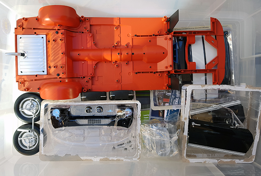
23/4/2017 – question answered
We have been asked via email a couple of times now how we store our model. So we decided to share it with you. We have a large plastic storage container that we fit the car into. The doors and other parts we keep in their original moulded packaging.

Update 4/6/2017
Double month for Issues 73 – 80
Parts 73 – 76 first.

Part 73
We continue to work on the engine block with the other half now being supplied. Pressing the two halves together and screwing in place will make the block. On the back of the block the curved part of the gearbox is also screwed into place. The radiator also now gets its mount to be screwed onto ready for the right side inner fender.


Part 74
The bottom of the block takes the previously built engine top end of valve covers, carbs, air filter etc and placed on top of the engine block. The oil filter is clipped into place on the side and is all held together with a flat plate to enclose the bottom of the block with two screws. There are some water hoses and breather pipes which are also now pressed into place on the top of the intake manifold. We notice here that one end of the water hose just flaps around under the air filter and not attached to anything in particular, OK you wont see it, but it’s a little shoddy. One of the pipes are pressed into the top of the transmission and located into place.


Part 75
The bottom of the oil sump is a single screw to hold it in place on the bottom flat plate. More wire now for the engine, is where we noticed a serious issue with the HT (or speak plug) leads are in completely the wrong firing order, why they did it like that is a little odd to be frank. The distributor pressed into the engine block and each half of the HT leads are pressed into each side of the engine block.


The ignition coil is pressed into the front of the engine block after the end of the wire is firmly located into the centre of the distributor cap. The final part is to clip each side of the exhaust manifolds. The main part of the engine is now complete.
Part 76
The right side inner fender is next with the shock and spring also being fitted. The first part is locate the inner part of the shock to the suspension and press the pin into place with pliers to hold it there. Mount the engine into the engine bay and with two screws through the gearbox tighten into place. Make sure the exhaust manifolds sit in the exhaust pipes already in place.


The inner fender will house the battery for the electrics which is cleverly hidden under the Autolite battery. Nice touch. Place the outer shock into the gap on the inner fender and screw into place. Next take the radiator and the mounting bracket and screw into place on the inner fender from part seventy-three earlier.

Now take the suspension spring and place over the outer shock cover and lower into place on the chassis. Make sure the inner shock sits into the outer cover and arrange the fender to line up with the holes on the chassis. Start at the front and work back just enough to hold the fender in place. When you are happy then tighten all the screws up. Now we can connect the radiator hoses to the engine block and manipulate the fan into place.


Issues 77 – 80

Part 77
We found it a lot easier to remove the splash guards for this section as the screws are particularly covered by the guard. This sees us now with the engine bay fire wall. There is a the brake booster and that has the master cylinder pressed into the front of it. Clip the booster into place on the front of the fire wall and the single screw behind holds it into place. Slot the firewall into place behind the splash guards in front of the inner cabin and screw into place with the two screws onto the inner fender. Now you can replace the splash guard. Once the fire wall is secured re-attach the splash guard. You can see the two screws at the bottom of the first pic below.

Part 78
Again remove the splash guard this side too as it’s a lot easier to secure to the fire wall. Here we have the right hand side of the inner fender just like issue seventy-six. Screw the outer shock cover in place as before. This fender will host the circuit board and the speaker for the sound. Insert the speaker and secure in place with the cover and two screws.

The same process now to insert the inner shock to the suspension and press into place with the pliers. Lower the inner fender into place making sure the spring is over the shock cover and locate into place on the chassis, check to make sure the inner part of the shock stays inside the cover and the spring. At the front the inner fender will screw to the other side of the radiator and hold it firmly in place. Again manoeuvre the fender into place and locate to the chassis holes. Starting from the front tighten up the screws. The two screws for the rear fire wall can be accessed and screwed into place. Now replaced the splash guard and re tighten back up.


Part 79
this is a beautifully detailed section of the model. We have some easier parts to assemble and only took a few seconds. The Battery has a bracket over the top which just clips into place secured underside with a couple of small screws. The battery can be placed onto the inner fender now as this will cover the actual battery for the model.


The export brace is firmly pressed into place onto the top of the shock towers.


Part 80
Press the water jet bottle onto the left side inner fender. Now we get to the models electrical circuit and wires, this actually looks worse than it is. There is a circuit board which which has slots that need the corresponding wires to be attached to it.


The cables are numbered and can only be inserted in one direction. Insert all the cables as labelled. With all the cables in place connect the remaining speaker to the board and screw into place under the top of the inner fender.


Gently arrange the cables to be kept tidy by the clip at the top of the inner fender as per the picture above. Now take the wires previously number one to five and connect those again to the corresponding wires you have just routed to the cabin area.


Some cables are long enough to be hidden between the back of the fire wall and the inner cabin area. The only part we didn’t like is this single power wire from the right side fender that just flaps about above the wheel as it’s routed to the circuit board connection. We suspect that a little model glue will be used to neaten this wire up.

The completed and wired up sections so far.

Update 23/4/2017
Issues 65 – 72.


Part 65 & 66
We covered these together as the part 65 is just a single piece of the back of the trunk area with nothing to do. But part 66 will add to that part and make the sides. Basically they press together and locate on the pegs at the back of the rear chassis rails. Part 66 also has the spare wheel lock that now enable you to locate the wheel in the trunk correctly too.


Part 67 & 68
For now we forget the car and can be put back in a safe place. Now we start back on the engine from the first few issues. We start on the rear of the radiator where part 67 has the viscous fan coupling and the back radiator grill. We insert the viscous fan and the metal grill over the back section where a single screw will hold the central viscous in place via a key-way. Part 68 has the rear shroud held in place by four additional screws from the inside. It is important at this point that the shroud is located CENTRAL to the viscous fan. You will see that there is a different sized gap when the shroud is fitted either way up. We found that fitting the fan to the viscous coupling in the middle is the best way to see which way it fits. When you are happy then screw the shroud into place.


Part 69
Then next part was the top of the radiator and pressure cap. It’s at this point we had a screw failure. The pressure cap is located into the top of the radiator section and single screw underneath the top of the radiator will hold it in place. The metal moulding was very tight and wrung the head of the screw. As this was not a stress point it was a simple small drop of super glue to hold it in place.


Clip the top of the radiator on to the back section of the radiator. Snap the front of the radiator onto the back section ensuring the pegs are downwards. The front metal grill will only fit one way and is held in place by two small screws in opposite corners.


Part 70
This part has the front of the engine block made of metal in Ford blue.

The front of the engine block has a bracket screwed into the rear which locates on the cylinder heads on part 72. Screw the bracket to the back of the engine front. The powered steering pump screws to the silver clamp and also secured from the rear by a single screw. The last part is a the small pipe that presses into the top of the engine front.


Part 71
This is the part where the pullies, radiator hose and alternator parts are fitted to the engine front. Both the alternator and the top hose are in half and pressed together. The alternator is located to the opposite side of the of the power steering pump. The top radiator hose is pressed into the top section of the radiator and will only fit in one position due to the key-way.

The pulley system is located to the front and screw passed through to also hold the front fan in place as well.


Part 72
Here we have the right hand side of the cylinder head, exhaust manifold and some wiring. The wiring is an on/off switch for the car’s electrics. This is installed just under the gauge dash on the left hand side. the wires need to be gently bent over to the clamp to hold it in place. Press the switch firmly home first to get it at the correct angle. A single screw holds the clamp in place.


After fitting make sure you can move the switch up and down without the body of the switch moving. Here we have just pressed the front onto the cylinder head to show the location of the bracket.


You will have the radiator, cylinder had and a manifold all as loose parts to be stored safe and sound.
Update 19/3/2017
Issues 61 – 64.
It seems as though We had a long break before our next instalments of the GT500 model, but at least we got them now.

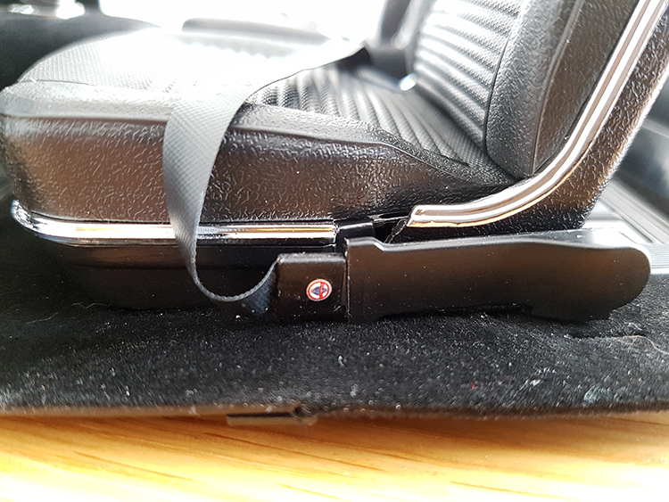
Part 61
The rear seats and seat belts on this issue. As per previous issues we are not fond of the way the seat belts pin to the underside. Again we used a little superglue to hold them in place as the little lugs didn’t seem that good. At least it can’t be seen on the underside and just gives a little piece of mind. Just make sure you get the right buckle and clips around the right way.


Place the seat into the back and screw into place.
Part 62
The rear carpet section is in two halves and clips together. Place into the back and two screws behind will hold it in place. Next are the two little clips for each corner, again held in place by smaller screws.


Part 63
We were quite excited about this issue as we see the steering wheel for the first time. This has the wired horn section and the bottom of the steering rack to be fitted.


The bottom cog is tight to the steering column shaft and needs to be tapped fully home.

The top of the steering column is in two halves the bottom half will hold the micro switch for the button. It took a little bending of the wires to make it sit correctly.


The top cover of the section steering column is three screws to hold it in place. The steering wheel itself just pushes of the other end of the shaft, with the horn button clipping into place.


We found the steering wheel does not sit perfectly square and with a little pulling will come straight back off the shaft. We would like to have seen a support screw in the middle here of some sort to be honest. Perhaps a little super glue later on? The quality of the steering wheel is very nice though. There are a few parts left over from this issue so keep them safe as they will be used later apparently. It looks like the steering column support bracket and bottom grommet to us.
Part 64
Dead simple this as we have done it before, the spare wheel. Two parts only pressed into each other.

The rest of this issue 64 is to put the inside cabin to the floor pan and chassis. From issue 63 there is the steering wheel that needs to be attached to the dash. take the steering column and ease it into place through the square hole in the fire wall. we undone a screw above the hole to make it easier to slide the column into place.


With the column in place press it up into the cavity making sure that the screw hole is in the middle of the location hole. Press the locating ring pegs into either side of the column and then screw into place.


With the column in place we will see how good and well you made the two pieces as they attach together. the end of the steering column will have the cog which sits on top of a toothed plate. Make sure the steering wheel is in the neutral position and the wheels are facing forward. Press the cog down into the chassis and locate the bottom of the interior cabin onto the four locating holes. Press the black steering box cover plate over the cog and plate and gently turn over to screw the cabin to the chassis with the screws.


The two parts are now together and the moving the WHEELS and not the steering wheel, the steering wheel should rotate each way. The steering wheel is NOT man enough to turn the wheels on its own. If you try it, the steering wheel will come of the column!


Update 22/1/2017
These issues are 57 – 60.
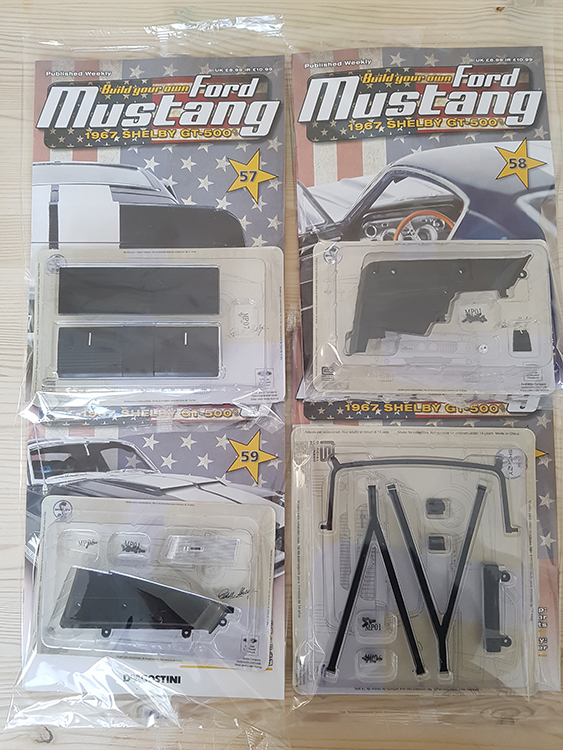
Part 57:
This issue is a the rear seat back that will screw to the shelf from the last issue. Just press the two parts together and they will snap into place. Tiny screws again for the hinge, but they look good.
the completed shelf seat lays onto the back of the rear section. There is a notch in the lower sides of the rear panels which will take the hinge pin.


Part 58:
This is a duplication of the previous issue Part 53 for the lower side trim.


The tricky part here is to get the rear seat/shelf to stay in place while you screw it together. A down side here is that the plastic has bowed outwards slightly and the tolerance for the hinge pins into the trims means it pops out a few times. We suspect that when it all bolts to the car it will all tighten back up again.


Part 59:
This is a duplicate of the Part 54 for the top rear trim. Getting everything to align while trying to screw it together was a little bit of a mission though.


These pics are of the three positions of the rear seat/shelf being moved.


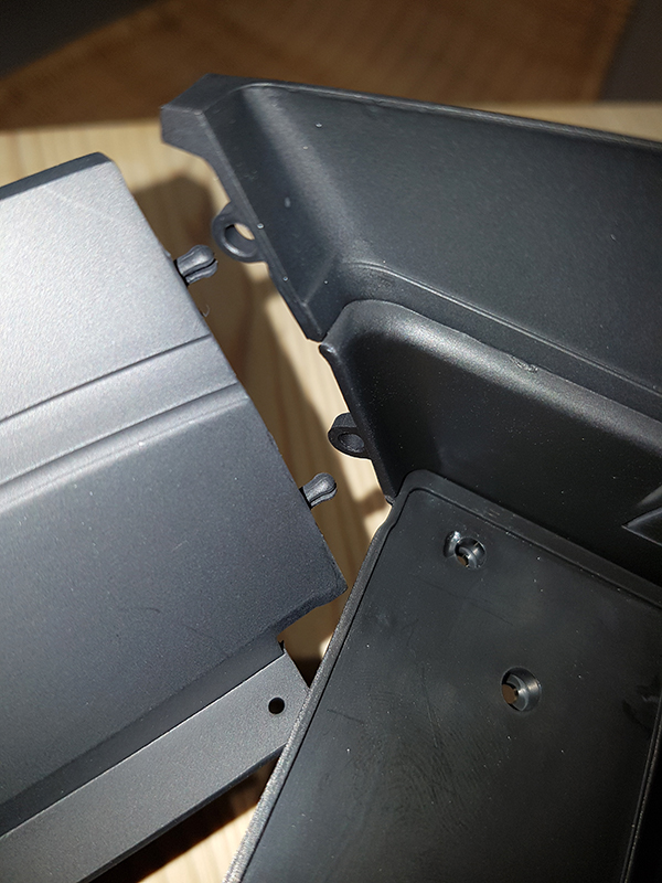
Part 60:
This issue was a real fiddle with the rear harness belts. The first job is to fit the under dash heater box with two screws.


There are to roller blocks that are mirror images of each other. This image in the magazine was not brilliant but there is a “R” and “L” on each roller if you get stuck. The seat belts have to be threaded into the slots of each roller and the metal part of the hinge lays in place to allow a small screw into the top roll cage fitting. This is repeated for both sides. Depending how OCD you want to be about this, but look at which way the belts will show, specially at the outer side of the belts near the floor. The could be the lapped over material showing if you get it around the wrong way, will it show? I doubt it, but we made sure the glued section was at the back of the belt and not seen from the front.


The roll cage is clipped into the lower rear trim and a small screw holds it in place. The bottom sections of the of the belts are slotted into the base of the floor section. They recommend to use small pliers or tweezers. We found it easier to get the fitting part of the way through the slots and then gently press it through with a small flat screwdriver. The choice is yours of course. From the other side the metal fastener will clip over a pin to hold it in place. Another down point here. We found that these pins were a little short and didn’t have a nice click into place feel.


We made a decision here to place a tiny drop of super glue onto the pin with the fastener to make sure it stayed in place on all the seat belt anchor points.
The finished article is pretty good detail but takes a little while to get it all in place.


Update 08/1/2017
These issues are 53 – 56.
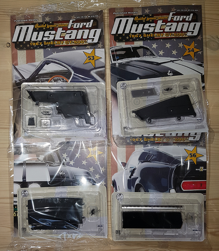
Part 53:
We continue with the inside theme with the first of the rear trim sections which comes in two parts, this being the first. There are two simple parts to screw to the trim, the courtesy light and the latch. With those in place a further three screws holds it onto the floor pan we have been building up over the last few issues.


Part 54:
This issue has the upper part to be attached to the previous lower section. The trim is a single piece with three screws to the rear, of which one is a lot smaller than the other two towards the front of the trim.


Part 55:
This was a single piece to be fitted to the left rear trim and under the rear floor pan. You can see that part has rounded fittings which push into the both the upper and lower parts of the rear trim. We were frustrated here as the parts didn’t align correctly and took a little bending to push them into the holes. Once they were in place a simple three screws to hold it firmly at the underside of the floor pan.
Part 56:
This part we liked a lot. The fold down shelf has a hinge and this is replicated in metal with very nice detail. There are chrome coloured screws to match the metal hinge which is located by a very slightly of set centre screw and will only fit one way. Once the hinge has been screwed on there is nowhere to attach it at the moment. These hinge screws are really tiny and we hope you have a nice set of screw drivers to cope. We found that our magnetised smaller driver fitted perfectly and made life a lot easier to attach the hinge.


Update 25/11/2016
Half way through the build.
These issues are 49 – 52.
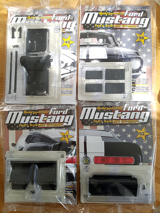
Part 49:
This issue provides the rear foot-wells to be screwed to the front floor panel. The seat belt buckles are the first part and just press into the out sides of the floor.


The seat-belts themselves are a ribbon and completely flexible. They are pressed into the floor pans and pulled through to press over a pin.


We found that one of the seat-belt ends was a little frayed but still went in OK.
Part 50:
This issue sees four rubber mats being pressed into the holes in each of the foot-wells and took a matter of a minute or two. they can only fit in one way due to an oversized pin on the back of the mats.


We now go back a few issues to pick up the seats we previously assembled. They will now fit to the front floor pans via two screws underneath the floor pans.


Connect the seat belts to the buckles on the outside of the floor pans. At this point we noticed that the seat belt buckle does not fit correctly to the outside floor anchor buckle. It moves out of the way very easily if knocked. The other side holds in place fine.
Part 51:
The rear seat platform is attached to the rear floor pan now via four screws. Again a dead simple effort that took a minute or so.


Part 52:
This issue will attach another part to the rear seat base you had just completed from the previous issue. Three screws this time and a matter of minutes to complete.


The images so far at the half way point. although we haven’t been told to fit the inner floor pans yet we can see where it will be fitted.


Update 23/10/2016
These issues are 45 – 48.
For this months issues the car chassis stays in storage while we concentrate on the dash gauges and interior for a little while.

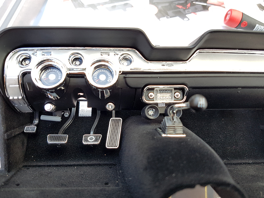
Part 45:
Things are getting exciting with a our first view of the electrics that will be a part of this build. There are two micro switches that will be behind the pedals, one for the gas and the other for the brake pedal. The switches are labelled as “01” and “02” for connections later. It’s a bit pf a fiddle to hold the switches in place while screwing the bracket to the floor without the switches falling out.


Side kick panels are also added in the same black velour material. When fitting the pedal assembly make sure that the bar on the back of the two pedals seats correctly in the holes. A slight press of each and you should feel the switches activate.
Part 46:
This was a single screw to hold the ash tray to your new dash pad area.
Part 47:
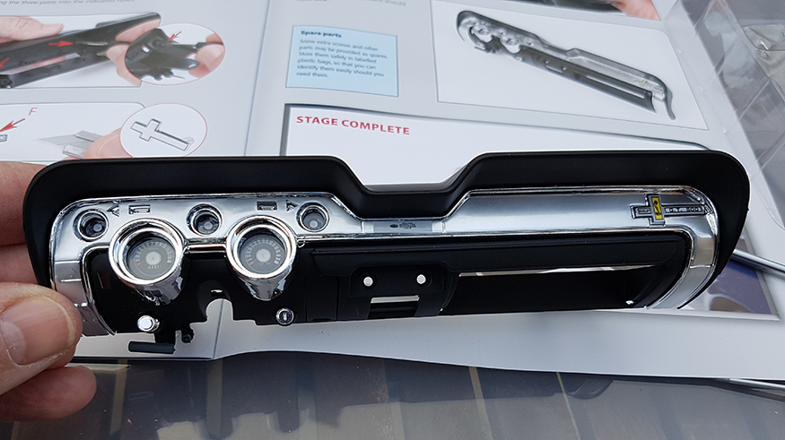
Some pretty internal parts now being fitted in the shape of the gauges. There are multiple stickers for the gauges faces themselves. The instructions suggest using the sharp point of a craft knife to locate them. We found that a tiny flat blade screw driver would not mark the decals and would also allow you to rest the decals in place and move them around before final pressing down. Take a good look at the printing of these decals, we found that they were printed slightly off centre so we had to move them down a fraction to make sure they would show in the centre of the pod gauges.


The next part was to fit the gauges lenses and the brushed aluminium cover using a number of small screws to hold it all in place. The Shelby badge also needed to be screwed into place.


Part 48:
More decals now for the gauges under the dash using the same principles as before. The radio is a pretty cool part and shows attention to detail. The glove box on fits into a hole each side of the dash pad and should allow it to open and close. This fitting is not the best part of the build so far, but then again i doubt very much it will be used a great deal to be honest.


The finished dash area looks pretty amazing as we have come to expect.
Update 9/10/2016
These issues are 41 – 44.

Part 41:
This centres around the front suspension lower control arms and sway bar. The main part is a large piece and is screwed into place on a number of places. Not a lot of parts, but a fair amount of time to fit them all together.

Lower control arms have the press in pins which will need a pair of pliers, we also prefer to press the pin is from each side protecting the frame with a small piece of card torn from the packaging.


The previously built front wheels and steering are used now to screw to the control arms. The chassis will need to be flipped over and back a few times. The only tricky part here is steering ram on the chassis to be connected with the steering on the wheels.


Part 42
This issue centres around the top control arms holding the wheels in place. The parts again need to have the pivoting pin pressed into place with pliers.


The single screw will hold the control arm to the wheel and should now move up and down with the car. Two screws for each side of the frame rails and need to be fitted uniquely for each side.

Part 43
This is the exhausts running from the rear up to the front section now. There are the main pipe and the other half of each muffler to be to be screwed together, they can only fit together one way. We found that the rear pipes that go over the rear axle have a cut out where the exhausts fit into. We noticed that our was a little out of shape and needed a very gentle bend to get the ends to seat correctly. If you do bend be careful not to break or snap them.

The exhausts are held in place by four screws on the inner side of the floor pans.

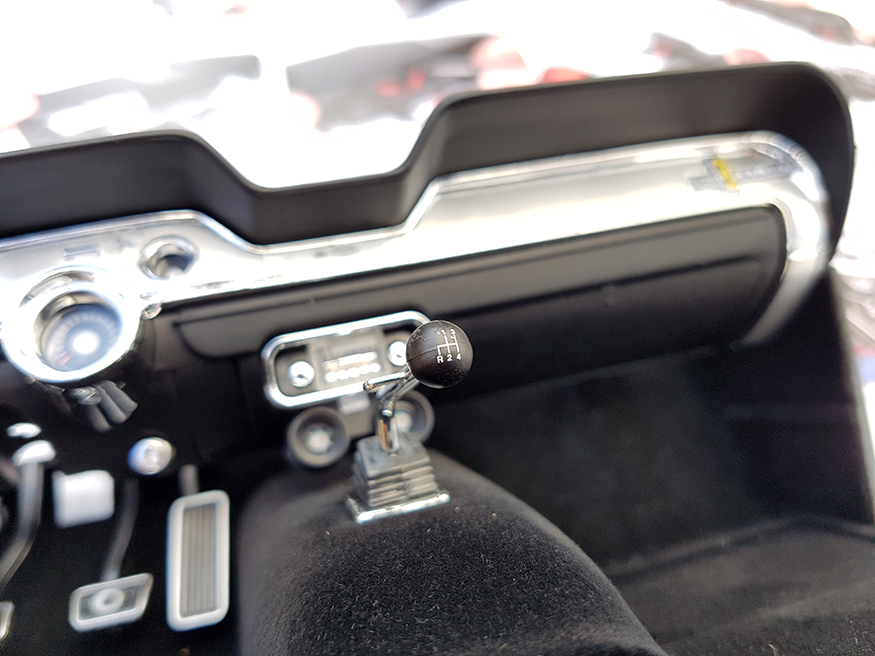
Part 44
This sees the first part of the interior to be fitted, apart from the door cards that is. The front carpets if you like and the gear shift. This is a single screw from the underside of the carpet. The black section is a superb black made of a velour style material.


This part is not attached to the floor pan itself yet but you can see where it will fit though.

Update: 11/9/2016
Parts 37 – 40

Part 37
Simple case of adding the front chassis to the middle section. 4 screws and job done. This gives us the first indication of the length of the model. The second pic here shows a corresponding magazine laying next to the model. It’s going to be approx two A4 magazines long to put it simply.


Part 38
These couple of parts are the first upward build of the base chassis. again very quick with only four screws.


Part 39
This is the first part of the steering to be assembled. Once it has been completed the two front wheels will be attached to each other. The metal steering parts are held together by a couple of screws, but should be able to be moved so don’t over tighten them.


The steering has a few left/right side bespoke parts, these will be attached to the wheels from the earlier issues and will now need to be retrieved from storage. Again these parts will need to move so no over tightening.


Part 40
Part chassis and part steering with this issue. The chassis has a couple mounting brackets which are screwed to the chassis which are generic to either side. The other part fits on the chassis in only one place.


Back to the steering again with the wheels, the remaining part of this will screw into the middle section of the steering. We found that the screw hole was a real tight here and had to have a couple of attempts to try to get the screw seated correctly. Perhaps a little paint got into the hole.


Now we have almost the full length of the model you can see how we store ours ready for the part of the build.
Update: 19/8/2016
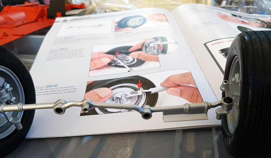
A big update this time with a good couple of months worth of builds. There are some duplicates here like the rear wheels and the rear suspension leaf springs. The principles are exactly the same so I won’t repeat myself on those, but you will get the general idea.
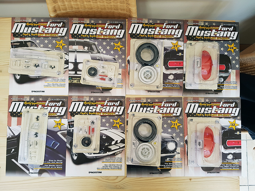
Parts 25 & 26 + 29 & 30
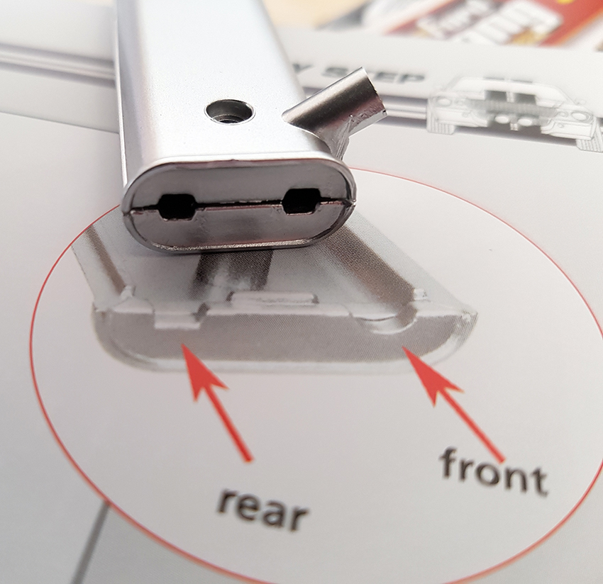
These issues deal with the rear suspension set up and secures the rear axle in place. There are some very intricate bits here and the pins into the top part of the shocks have to be pressed into place with a pair of pliers. Note which way round these brackets fit on the end of the leaf springs as they fit the chassis rails, and also which end they are applied too. These top of the shocks are angled so you need to make sure which way round they sit too otherwise the shock sections will not meet correctly.


In the issues 25 & 29 they tell you to secure the axle’s shock mounting plate in place, then in issues 26 & 30 they tell you to remove it and then add the shock bottom section to it. We found this a bit of a mess. So we had both issues open 25 & 26 then 29 & 30 to mix them both together so it’s only fitted once. The shock plate also gets in the way of fitting the shock top to the floor pan too where they suggest you use tweezers to put it in place.


Parts 27 & 31 + 28 & 32
These are the rear wheels, exactly the same principles as the front wheels, heat them up with a hair dryer to supple the tyres up and then press the rims into the tyres. From the parts 26 & 30 there is the brake drum components, locate these to the inside of the rims and fit over the rear axle. A single screw will hold the wheel in place and cover with the centre caps. Parts 28 & 32 are the inner wheel arches, just three screws each side hold them in place, a dead simple set of six issues.


With the parts all in place the rear section will stand on its own and you can get a lot of the parts located onto the chassis and tidy up the box of parts you have.


Parts 33 – 36

These issues see the floor pans moving to the centre sections and the prop shaft, gearbox housing and gearbox brace. Part thirty three see’s a large section which has a few screws to locate it to the front section of the rear chassis.

Part 34 see’s the centre tunnel continue up to the front section. We found this was a little tricky to locate all in place so we put the screws in and only just caught the threads to allow any adjustments. tightening the back down lifted the front and was awkward to locate. with no pressure on the screws you can just tighten them all up once they are in place.


Turning the model over now will allow the prop shaft to be fitted in place. This comes in two parts and his held in place by two screws from the floor pan.


Parts 36 sees the gearbox housing and the brace fit into place. again dead simple with only a few screws to hold in to the floor pan.


Completed so far.

Note:
We are so far impressed with the quality of the plastic part mouldings. We have not had to file any rough edges or plastic lugs of to make things fit. Within this last update we again see the instructions flick between screw part numbers “MD01” or description of the screws which can be annoying at times.
Update: 10/7/2016
We haven’t updated for a little while now as the last batch of issues have been more, doors, seats, wheel, fuel tank and chassis parts. The previous issues will cover those builds and to be honest it’s little pointless to duplicate those builds. A lot of those parts couldn’t be fitted together just yet until this latest batch of parts.
So we jump to parts twenty one onward where we suddenly start to see things being built instead of a box full of parts.
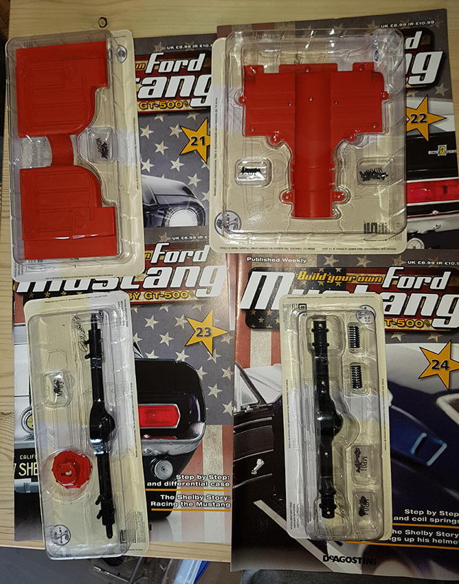
Part 21
We have fitted the fuel tank from a previous issue that is just held in place with four screws to the main rear chassis. Part twenty one sees four screws holds the chassis and the first part of the heavy metal floor pan parts together.


Part 22
This issue has another floor pan part this time in plastic with quite a few screws.


Part 23
We now see the exhaust to be fitted underneath which is a little tricky to hold in place and screw into position.

Part 24
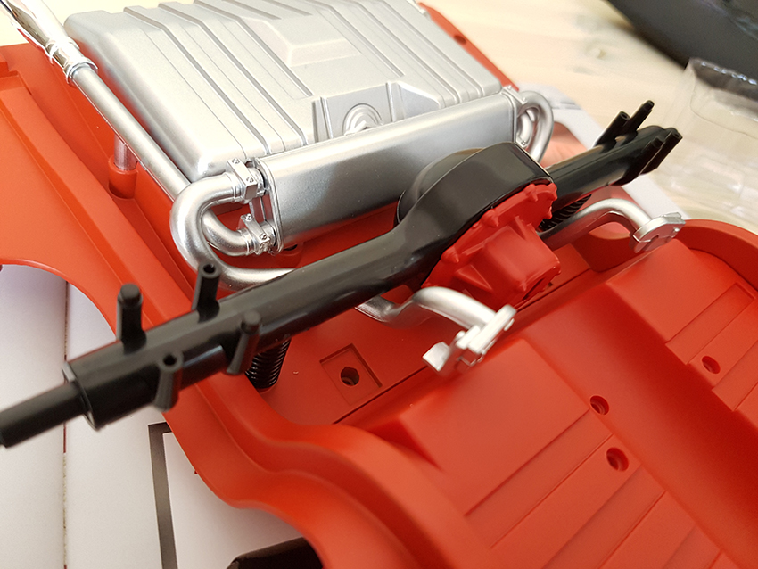
Parts twenty three and four will assemble the rear axle and diff together.


The final part here is to fit the rear axle to the chassis. The rear axle has working springs that will allow the axle to move under the chassis.
Update: 29/4/2016
We can say that storage of the parts needs to be done with care now as we have a large box box that can now contain the parts safely. The exhaust from issue six being the most delicate so far. We are keeping the original packaging where we can, cutting it about a bit and storing the parts within them to keep them safe.


Part 13

Not much to say about this issue as it’s the right hand door and exactly the same as Issue 9 only the other way around.
Part 12

This issue adds the back to the left hand side front seat. very simple with four screws.


Part 11

This issue continues the work on the inside of the left hand door. a couple of tiny little bits here, the worst being the door handle that has to go in loose the tightened from the inside before the trim is fitted. There is a request to use the screw described as MP06, the pack supplied was MD06. The screws still fitted but we wish they move away from the description of screws and use the codes on the bags.


Part 10

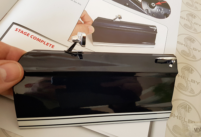
This issue now completes the bright work for the left hand side door. We ignored the instructions here a little to add the door hinge first as that would save having to hold the door and the plastic itself, thus making it easier to handle.


Just make sure that you get the hinge round the right way, complete section.


Update: 10/4/2016
Part 9
More body work now, this is the left hand side door.

Dead simple this one to add the mirror and the door handle. You again get to see the scale of the model. We noticed a shift in instructions, previously they mentioned “MD02” or what ever the screw was to be used. Now they mention this by size, although it’s not a problem, it is a pain to keep having to check the screw sizes to be used.


Part 7 & 8


These issues are the same as Issue 2 for the other front wheel. Not sure why this is now two issues but as you get them together it doesn’t cause much of a problem.


Part 6
This issue sees the construction of the rear exhaust system.


This part was a little bit of a fiddle to get the exhausts lined up correctly before screwing the silencer box up tight. We spotted a slight error in the casting/printing where they mentioned the two different shaped holes for the exhaust, there isn’t as the are both the same.
The finished item is going to be a bit of a pain to store until it’s fitted to the car.
Update: 6/3/2016
We have received the next batch of magazines for this model all be it two this time. We understand from others that are building this model that everybody should now be at the same stage and the batches of four issues will continue from the next delivery.

Part 5

This issue was a very simple section of the left front seat back rest. This came in three parts and is held together by a number of screws at each corner. They do offer the advice to use model glue for extra strength if you want to, but we found the snap together a good enough solid fit. You can see from the detail on the seat finish they really have made some excellent tooling for this level of quality.

Part 4
In this issue we have been supplied with a huge slab of metal that is the hood. It’s heavy and gives you a rough idea of the scale of this model as the hood is getting on for the size of A4 magazine it comes with.


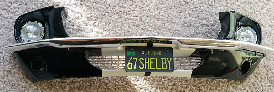
The quality of the paint is pretty amazing for a model, we have tried to show the corner of the hood in detail here. Along with the hood comes the rest of the front grill will is screwed into your previously stored front section from part 1. The detail is top quality and intricate to say the least. The spotlights are pressed into the radiator grill and held in by small metal flaps to hold it in place. We would suggest that you do this once as repeated pressing of the lights could weaken the grip.


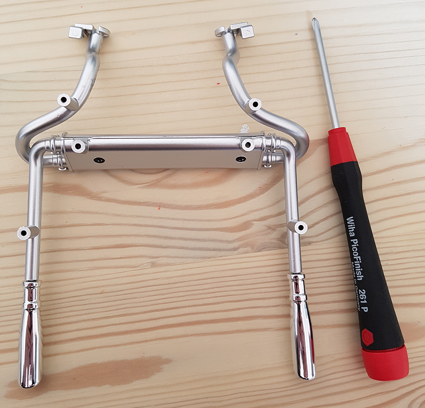
Before we start.
The second issue was supplied with a tool to put the model together. Now this may be OK for some but we found the screw driver slipped on a tight screw fit. So we got out the good tools a set of Wiha top of the range precision drivers. We magnetised them to hold the screws and this made the whole process much, much better. We recommend getting some real nice screw drivers, they are longer, nicer to hold and have a nicely engineered blade section. Some of the tiny screws are about 1mm in size. The supplied tool will do the job, but it didn’t suit our big hands.


Part 1 issued 9/10/2016 in a promotional pack


Update 24/1/2016 (Parts 1 – 3)
Part 3
The top part of the engine block supplied here, air intake, twin carbs, valve covers.


Completed:

Part 2
The Left side front wheel, the parts.


The tyre is in fact a very heavy rigid plastic, to make it fit you need to have a hair dryer to warm it up. They say a little heat, but we found that it was a gradual heat up till it was quite warm to get any sort of give in the moulding. It also cools pretty quick and when it does it becomes rigid again. The last picture below here shows the comparison of the supplied screw driver and the precision ones we are using.


Completed:

Before we start.
The second issue was supplied with a tool to put the model together. Now this may be OK for some but we found the screw driver slipped on a tight screw fit. So we got out the good tools a set of Wiha top of the range precision drivers. We magnetised them to hold the screws and this made the whole process much, much better. We recommend getting some real nice screw drivers, they are longer, nicer to hold and have a nicely engineered blade section. Some of the tiny screws are about 1mm in size. The supplied tool will do the job, but it didn’t suit our big hands.
Part 1
The start of the project is the front of the car, grill, headlights, bumper etc.
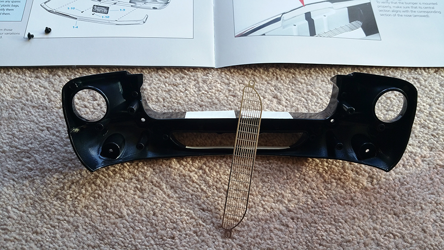
The headlights are incredibly well detailed and do indeed have a correct side for fitting.


Completed:


how many issues are in this series?
LikeLiked by 3 people
Hi, we believe it is running for no more than two years, or 100 issues. Considering we are almost 6 months into the build already time flies by. We have had another batch in, but haven’t had time to build and take pics of it so far. But, we can say it is a very good quality model, and no we are no on commission from them. 🙂
LikeLike
Hi guys,
me and a friend are building this also and i must agree the quality is great, i’ve noticed a couple of mistakes in the magazine where it tells you to put a part one way and then in the next issue its the other way up in the picture, ie the red part on the rear axle,
i also found the door handle can scratch the inner silver panel so i placed a small piece of a kitchen sponge under the handle when i built the second door and that stopped it happening. loving the clear pictures your doing its a great reference for me as i’m currently running 4 issues behind you 🙂
keep up the great work guys
Regards
Mr Ruszkai
LikeLiked by 3 people
Thanks Mr Ruszkai for your comments. We tend to get a load of parts then do them all at the same time ie every a couple of months. We also noticed the door handle scratch, we got round that by a little piece of paper between the door card and the handle. The think that annoys us is the screws are marked as numbers then the instructions mark as screw size, you constantly have to keep checking. We do like the fact you get a spare screw with the packs. We have dropped a couple and been able to use the spares. We are over a third of the way through now and can see the floor pan taking shape nicely.
LikeLiked by 1 person
Hello, very nice article, here in mexico we are just starting (4th issue) and i have a question, is it possible to buy 4 number 2 issues? i see the spare wheel is different but besides the suspension and disc brakes (wich are not supplied in the issue 7, 31 and 37) are they the same? this is of particular interest to me because issue 2 was 99 pesos but starting issue 3 its 220 so it could be a way of saving on future issues? thanks
LikeLiked by 1 person
Hi, in theory you can order as many back issues as you want from Deagostini. I’m not sure if they will sell them all at the reduced prices. You would need to contact the directly for your answer. I have noticed in other countries that the order of parts is different to the UK.
LikeLiked by 1 person
Yes i can get the other issues (i have a contact) the question was if the tyres (or rims) are the same so that i can buy all at once, thanks.
LikeLiked by 1 person
The five wheels we have put together so far have all been the same size.
LikeLike
Hi All, glad that l have found a site with other interested people on this Mustang project.
I am in Sydney, Australia and have just received issues 9 to 12.
I am not a F**d fan, but have loved Mustangs since a kid over 60 plus years ago.
The quality of the model so far has been excellent, and just the design/engineering to make this model is truly amazing, credit to all involved.
As l have only found this site this morning, and looking through future issues is very exciting for what is to come in coming issues.
Will be interested to follow issues/problems that others have faced during the build, such as the door handle, which l only put together yesterday, LHS, driver door.
Looking forward to hearing from others
Great building
Ross
LikeLiked by 2 people
Hi Ross, thanks for the comments and dropping by. The model is a great quality piece. Issues 85 and on we have been waiting for well over a month now hence no recent update.
Enjoy tHe build. 👍
LikeLiked by 1 person
Where can you get this kit, and can you buy it our right or is it that you get certain parts each month, and it will take a year or two to build I want but dont want to take two years to build!!
LikeLiked by 2 people
Hi, the kit is made by DeAgostini and the links are in the page. As far as we know it’s only per month. But that is for the first subscriptions. Once the full model has been made who knows you may be able to buy it in bulk as it were. Email and ask them. 👍
LikeLiked by 1 person
I am ready to test the electrical system before final assembly but need the battery specs and where to get them..
LikeLiked by 1 person
You can get the batteries from any super market and is a very common size. LR44 or AG13 as you can see in our pictures on the page.
LikeLike
My Mustang is ready to assemble the top and bottom .I would like to test the wiring before the final assembly. The quality is outstanding.
LikeLiked by 2 people
Hi the batteries are LR44 or AG13 you will need 3 of them. You can see the batteries from the pictures.
LikeLiked by 1 person
Hi my name is Steve Pahlke I am from Melbourne Australia I have built this model so far up to part 36 I am missing part 37 I have 38 missing 39 and I have part 40 up to 55 I haven’t received anything from this mob for over 2 months I was just wondering if they are still sending issues or is car a complete waste of time and money I have tried to ring the number on the cover and no answer so it has left me in the dark could you find out if they are still doing issues thanx for your time much appreciated great model so far
LikeLiked by 1 person
Hi Steve, we have NOTHING to do with Deagostini and we were customers jyst like you. We had issues with delivery as well on some occasions. Contacting their customer services is the only way to sort it out. Try Twitter and tag them with your problems and they should respond. The model is pretty good apart from the rubbish door hinges. Detail under the hood could have been better too. As for the ‘realistic’ sounds– they are rubbish to be honest.
LikeLike
Started build Oct 2017.Is now Oct 2020 & still building.Still have parts on back order.Over 2 years been waiting.Costomer help line don’t help at all.But have payed for 100 issues. ($2000.00)Payed excessive amount on eBay for parts just to get it done.But cannot find issue 98 yet.Anybody got a spare issue 98?.
De Agostini can go to hell in my books.
I do agree the model is pretty special.
LikeLiked by 2 people
They are not covering themselves in glory. We also had a couple of issues, but we started when it was launched so parts were plentiful. We have absolutely nothing to do with DeAgostini. We just documented the build over two years.
LikeLike
Just wondering where i can get the last 20 parts, car 3/4 built,
Maybe somebody can point me in the right direction
Thank you
LikeLiked by 2 people
We have absolutely nothing to do with DeAgostini we just documented our build. We suggest you contact them direct or look on eBay as a last chance effort.
LikeLike
Absolutely beautiful looking kit. It’s a real shame that the manufacturer seems to be so unreliable.
LikeLiked by 2 people
We agree. However you wouldn’t believe the amount of emails that we get complaining about the service. We have nothing to do with them what so ever. We posted about the kit thinking people would be interested. In fact it has caused us so much grief and aggravation we are thinking of taking it down.
LikeLiked by 2 people
Wish I had some good advice there. You can only repost the “we’re not associated with them” so many times.
LikeLiked by 1 person
I have to say it’s great to be able to read all of the above assembly hints, but I would like to know how I can obtain a missing issue…..I started building the car, & discovered I had not bought Issue #10 for some reason!….I have all the rest up to #100, but I need the Left Side Door Window & Hinges, which come with that Issue!
I hope you people can help me in obtaining the missing issue & parts!
Thanks for your time
Michael Hunt
mhunt48@bigpond.com
LikeLiked by 2 people
Hi, thanks for the kind words.
We had and still have nothing to do with DeAgostini, we were customers just like you. The only thing is that we were blogging about it so we got our stuff on time.
We have many emails trying to get issues for people, but we have no sway over them.
Our only advice is to check eBay. We have seen a number of full set issues for sale.
LikeLike
Well done…….I have a problem with my mustang model…….when I received issue 94…the company went bankrupt. Now I have an incomplete model and don’t know how to get the last 6 outstanding issues to complete it…..any ideas as I’m a resident of Australia….thanks…..Dave
LikeLiked by 2 people
Mustang Maniac is not affiliated with DeAgostini in any way. We get a LOT of emails about this model and problems. Our suggestion is to look on eBay UK as well as rest of the world. We have seen regular listings of various issues, some at cover price some at ridiculous money into three figures. At least you have the biggest part the shell which commands lots of money. It may take time but keep looking and browse model forums.
LikeLiked by 1 person
I am building the Eaglemoss Eleanor mustang. One kit is delayed over aahazone being out of stock. They refuse the shop the kit. Looking thru this post, I see kit #53. It’s the same as kit #59 by Eaglemoss. How can I aquire this #53 thru deAgostini? I really want it. Eaglemoss is sending me other kits beyond what I needed.
LikeLiked by 1 person
Oops Broke bonnet hood pins and radio arial. Where can I get replacements Please?
Mike
LikeLike
Mustang Maniac is NOT affiliated with DeAgostini. You would have to try and buy the magazine issues of Ebay if you can find them.
LikeLiked by 1 person
Thanks, you beat us to it. 👍
LikeLike
Hi, we had yo buy the model ourselves too. We have absolutely nothing to do with DeAgostini. As the reply says, you would need to contact them or loom for a complete issue or two by the sounds of it.
LikeLike